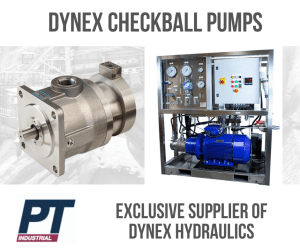
The Dynex range features products that utilise a Checkball. Commonly known as checkball pumps, ball-and-seat pumps or ball piston pumps, refers type of positive displacement hydraulic pump that is widely used in various applications where a constant flow of hydraulic fluid is required.
The main components of a checkball pump include a housing, a rotating element (such as a shaft or rotor), and checkballs (spherical balls made of materials like stainless steel, ceramic, or synthetic materials). The pump’s housing contains several cylindrical cavities or cells, each with an inlet and an outlet port. Within each cavity, a checkball is placed, and there is typically a central rotating element that can be driven by an external power source.
Here’s how a checkball works:
- Inlet Stroke: As the rotating element begins its rotation, it creates a partial vacuum in one of the cavities. This low-pressure zone causes the checkball within that cavity to unseat and move away from the inlet port, allowing hydraulic fluid to flow into the cavity.
- Compression Stroke: As the rotating element continues to rotate, the cavity with the checkball moves away from the inlet port and towards the outlet port. This movement compresses the hydraulic fluid within the cavity.
- Outlet Stroke: When the cavity with the checkball reaches the outlet port, the increased pressure forces the checkball to seat against the outlet port, preventing the fluid from flowing back into the inlet port.
- Discharge Stroke: As the rotating element further rotates, the cavity moves away from the outlet port, causing the checkball to unseat. The compressed hydraulic fluid is then forced out through the outlet port.
This process repeats for each cavity within the pump, providing a continuous flow of hydraulic fluid. The number of cavities and the rotational speed of the pump determine the overall flow rate.
Check ball pumps can feature fixed displacement (where the output remains constant during each pumping cycle) or variable displacement (where the output can be changed) and both applications can incorporate split flow depending on the application required.
To find out more about split flow terminology and what it means click here
For more information about the DYNEX range visit https://www.ptindustrial.com.au/dynex/
